Menu Close

Information

Wet welding rod for high carbon steel

Don:

As a follow up to our phone conversation today, the following describes the new nickel wet welding electrode we discussed.

The nickel wet welding electrode was developed to allow underwater welding of carbon and high tensile steels which would normally require underwater dry chamber welding.  These steels generally have carbon contents and carbon equivalents such that welding using carbon steel wet welding electrodes would result in cracking in the heat-affected-zone due to hydrogen embrittlement within a quench- hardened micro-structure.

The nickel electrode mitigates the effect of hydrogen and has resulted in successful under wet welds involving a broad range of high carbon equivalent steels, including HY-80 quenched and tempered steel used in Naval ships, with carbon equivalents exceeding 0.50.  The electrode has been used almost exclusively for U.S. Navy ship repair.  Recently, BROCO has developed an improved nickel electrode which produces welds with less porosity and allows deeper welding in the overhead position.  The end result is the potential  for performing underwater wet welding in applications which would normally require the use of more expensive dry chamber welding.  The electrode is appropriate for all position groove and fillet welds.  Testing to date has been to a water depth of 33 feet.  Test results exceed the requirements of the American Welding Society Specification D3.6 for Class B underwater wet welds and meet the more stringent requirements of the Navy’s Naval Ship Technical Manual NSTM 074. Typically, yield strengths exceeding 70 ksi and tensile strengths exceeding 80 ksi can be expected from the nickel weld metal in the as-welded condition.

Don, I hope this information will be helpful.  I will look forward to hearing more about the new testing facility.

Tom West
Director, Welding Engineering Services
337-896-6534

Ship Surveys in the Delaware River Bay

Due to security concerns, under water inspections may not be allowed at the dock. Please have your agent check with the terminal.

Underwater surveys of vessels in the Philadelphia area can occur in either the bay/ocean area or the river itself.

Surveys in the river have the advantage of not being as sensitive to bad weather such as moderate to high winds and accompanying high waves. The cost for launch service and transport time for the crew is significantly reduced. Unfortunately the visibility is affected by recent rain conditions and is never as good as in the bay/ocean. Under water visibility is generally worst in the Port of Wilmington area and gradually improves as you move either up river or down river from there.

Surveys in the bay/ocean have the advantage of the best available visibility. Unfortunately even a moderate wind can make it impossible to conduct a survey. Launch and crew transport costs are significantly higher.

Surveys conducted in either the river or the bay/ocean must be conducted during slack water as both areas have very strong currents that would make it impossible for a diver to hold himself in place on the vessels hull.

Cold Weather Pipe Line Operation

Special procedures are necessary for the operation of a spoils pipeline during sub freezing weather.

In choosing the size of the discharge line consideration of the input source should be considered. The larger the discharge line is relative to the size of the input source, the slower the discharge line is going to flow. The ability of the discharge line to carry material and resist freezing is directly proportional to the velocity of the discharge material through the discharge line. It is preferable to match the diameter of the source and the diameter of the discharge line as closely as possible.

If at all possible the discharge line should be graded down to the discharge. Given even the slightest of grades the pipeline will empty once the vacuum is broken at the source.

If it is suspected that the pipeline will not self drain, a “pig” can be blown through the line to push the water out. Any ball shaped object with an outside diameter roughly the same as the inside diameter of the pipeline can be stuffed in the pipeline. An air hose connected to a compressor of sufficient pressure and CFM is then connected to the pipeline behind the source. When the airline is opened the ball is forced through the pipeline forcing the water ahead of it. A cage to catch the pig should be attached to the discharge end of the pipeline, if not the pig will exit the pipeline with substantial force with the possibility of the pig getting lost or injuring bystanders. Foam balls of approximately forty-durometer work well as pigs. Long pipelines with low spots in their middle may collect enough water even after being pigged to form a plug. This can be remedied by installing a drain at the low spots to allow this water to leave the pipeline.

If for any reason it is not practical to pig the line it can be kept open by pumping water through it. The water should be pumped from well below the surface of the water to insure it is at least several degrees above freezing. As long as the water travels the length of the pipeline before it can drop to a below freezing temperature the pipeline will not freeze. Electric pumps are most practical for this operation as they can be allowed to run unmanned. Careful attention should be paid to the relative size of the pump and the discharge line as explained in paragraph one of this procedure.

In most cases it is not possible to bury the pipeline as it makes it inaccessible should it plug and is prohibitively expensive. Covering the line with hay bales or insulating it with construction blankets of the type used to insulate freshly poured concrete can achieve the same effect. Insulation in combination with the introduction of steam or hot water into the line is very effective.

Careful attention to detail and forethought make it possible to operate a discharge line in the coldest of weather with a minimum of lost time.  

Under Water Hand Excavation

Due to the cost of diver time and the inefficiencies of conventional pick and shovel excavation techniques when moved to an under water environment most under water hand excavation is done using one or more mechanical aids such as the jet hose, air lift, water dredge or hydraulic dredge pump. The following is an explanation of the benefits and limitations of these aids in the hands of a trained commercial diver. Please be advised that these tools can represent a significant risk to the untrained individual.

Jet Hose

The Jet hose in combination with a high pressure high volume pump and a reactionless nozzle will allow a diver to trench or level a tremendous volume of material in a short period of time. The hose most commonly used in the Philadelphia area is a 2 1/2”  fire hose coupled to a navy reaction-less nozzle. The navy nozzle has one main jet pointing in a forward direction and four smaller jets pointing back along the hose. It can be placed unrestrained on the bottom and with the balanced force coming from the apposing jets it will not move. Considering the weightlessness of the diver this is a great advantage. A conventional fire nozzle would force the diver backwards with a force equal to that exiting the forward jet. The reactionless nozzle allows the diver to utilize hundreds of pounds of force and water volume to move material. The jet hose  works best in softer material, rip rap, branches, and large pieces of trash will not of course blow away. It is also limited when digging deeper excavations as the material tends to fall back into the hole.

Jet Hose

Jet Hose:
Jet Nozzle Jet hose

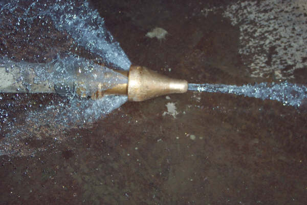
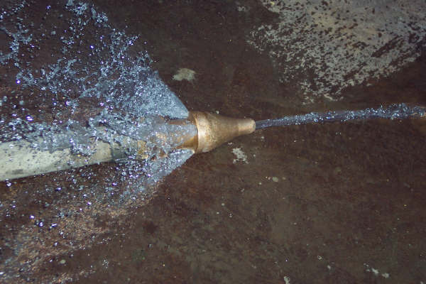
Commander Ellsberg of the USN tells about discovering the advantages of the reaction-less nozzle in his book about the salvage of the USN Sub 151 entitled “On The Bottom”.

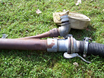
Many divers still prefer making a “T” nozzle out of plumbing fittings. Although a bit bulkier they work at least as well as the Navy Nozzle in most applications and have some advantages in others.

Air Lift

The air lift requires a compressor, an air hose and a long tube. When used for hand excavation the air lift tube is from 8” to 12” in diameter and 6’ to 10’ long. The air hose is used to introduce air into the water column inside the tube. This reduces the hydrostatic head inside the tube relative to the hydrostatic head outside the tube. The water rushes into the bottom of the tube and out the top picking up any sand, mud or small stones near the mouth of the tube as it goes. The more diffuse the water bubbles in the tube are the greater the differential of hydrostatic head. An air lift can be made on the job site by wiring a cp hose into the mouth of any pipe light enough for the diver to manage and it will work. An annular collar formed around the air lift tube with small holes drilled through the tube under the collar will give the greatest efficiency. In any case the air should be introduced within a foot or 18” of the bottom.
Air Hose

If the air lift should seal off the bottom opening such as when it sucks up a piece of wood or rock to big to pass up the tube it will become positively buoyant very quickly and head towards the surface. Great care should be taken by the diver to ascertain his umbilical is never in a position to be fouled should the air lift decide to take an unscheduled trip to the surface. Should the diver be pulled to rapidly to the surface he could experience a pulmonary embolism, sinus squeeze or ruptured ear drums. It is our practice to install a ¾ ball valve on the exterior of the lift as well as one at the surface next to the dive station. This allows the diver or the tender to cut off the air very quickly.

 If the diver finds that some of the heavier material is falling back into the excavation he can tie the top of the air lift down so that it leaves the excavation at enough angle to insure the material will fall outside of the hole. Alternatively a 45 degree angle and short section of pipe can be added to the top of the air lift tube. The material leaving the air lift will now shoot up and away from the air lift and in most instances will not fall back into the excavation.

Air lifts will lift materials well above the water surface. In some instances they are used to deposit material directly into a barge. The rule of thumb for figuring the height that an air lift will lift material above the surface of the water is two thirds of its’ length  submerged, one third of its’ length above the surface.

Air lifts are simple reliable excavation tools. They cannot be used in very shallow water. They do not transport material well in a horizontal direction.

Water Dredge

The water dredge requires several lengths of rigid 4” or 6 “ suction line, a jet hose pump, and a water dredge. The water dredge is most often formed from a metal tube with a fitting for  a 2 ½” fire hose to enter the side of the tube in such a manner as to force the jet of water up the pipe. The dredge can be placed at the end of the suction hoses or if the diver finds it more easy to maneuver the hose it can be placed in the middle of the hose sections. While not as powerful as the air lift and not able to break up and push material like the jet hose it has the advantage of being able to move material horizontally under water. This is often an advantage when digging deeper excavations or when not suspending material in the water column is advantageous. Water dredges are often used in combination with jet hoses. The  diver jets the material to the water dredge suction and the water dredge carries it some distance out of the excavation.  The water dredge will suck up a divers hand or foot as well as his umbilical . This is generally not a serious matter due to the relatively mild suction formed at the mouth of the water dredge. Still the diver should pay close attention to the relative position of the water dredge his body and his umbilical.

Dredge Dredge

Dredge Pump

A dredge pump is an electrical or hydraulically powered submersible pump fitted with a hose coupling on its’ suction side. A flexible suction line is coupled to the suction coupling and as many sections as needed are coupled to the discharge so as to allow the discharged materials to reach the spoils area. Roll flat hose is not used in either the suction or discharge side of the pump. Used on the suction  side it would immediately collapse and seal off the suction. Used on the discharge side it would work reasonably well until the line plugged. With a rigid discharge turning the pump off would back flush the line washing the offending object back through the pump and line. Roll flat hose sucks closed preventing any meaningful back flush.

The tender must have immediate access to a stop switch so as to be able to immediately stop the pump should any part of the diver or his umbilical be sucked up the suction hose.

Dredge pumps move great amounts of material in any direction. They are particularly well suited for de-silting intake bays inside of trash racks. Outside of trash racks they tend to jam frequently with debris making them very difficult if not impossible to use.

Bottom Surveys

Divers are often called upon to look for lost items or obstructions on the bottom. Unlike searches carried on above water the diver has limited if any visibility. Imagine looking for a five gallon paint can in an empty air craft hangar. Normally you would look around and go directly to the can. If however the inside of the hangar was pitch dark you would have to devise some method to methodically search the hangar floor until you encountered the paint can. Umbilical tended divers are most effective at this type of task. The diver stretches his umbilical out in the area to be searched and keeping it taught circles across the search area. If nothing is encountered the tender shortens the umbilical and the diver circles in the opposite direction. This allows the search area to be methodically covered . The diver knows what area has been searched and what has not. A scuba diver could approximate this method by using a rope in place of the divers umbilical. This method is of course time consuming and best used to search areas of high probability.

If the area to be searched is very large it is best to utilize a side scan sonar, or cable drag to locate likely targets. These targets can be identified immediately by the diver or marked with buoys for identification by a dive team the next day.

Low Water/Slack Water
Low water and slack water are often used interchangeably. This is not however strictly correct and if you are looking for absolute slack water with no current in a stream or river you will find that there is a significant difference between them. Low water happens when the tide recedes to its’ lowest point. At this time the stream still has the normal down stream flow. Slack water will occur some time later as the incoming tide exactly matches the outflow of the stream or river on that day. This of course can be affected by any event that increases or decreases the normal flow of the stream. A recent heavy rain will make slack water significantly later then low water. A drought would make it closer to the time of low water.

No Decompression Limits

The no decompression limits are a table listing the maximum time a diver can spend at a particular depth and return directly to the surface. Go beyond the no decompression limits and the diver must decompress prior to returning to the surface. This in itself is not particularly dangerous, the science of decompression is well understood and with modern tables a healthy fit diver can complete decompression dives regularly without risking any serious side effects.

In an industrial setting, divers are often working with power tools or moving debris in zero visibility. These tasks and others like them make an injury possible. If a diver is seriously injured while he is within the no decompression limits he can be brought directly to the surface for treatment. If he is injured while performing a dive in which he has incurred decompression time he would have to decompress prior to being treated or risk the possible fatal consequences of decompression sickness.

It is our policy to perform all tasks within the no decompression limits when possible. If this is impractical we will have an operating double lock decompression chamber on site during any decompression dive. This chamber enables us to decompress the diver in the chamber on the surface where any injuries he may have sustained can be treated.

Modular Float Systems

Our modular float system is made up of 22” square plastic Jet Floats. They are stored on their own trailer ready to go to work. Two men can unload them and put them together in less then 90 minutes. They can be assembled into a barge with a moon pool, a “T” head dock, a “U” to make any boat a powered barge, a sidewalk to get your work area or any configuration you may need. They are strong enough to drive a truck over and light enough to be moved and assembled by hand. Unlike conventional floats and barges each 22” modular cube is entirely isolated from the other cubes so if an accident punctures a few cubes the remainder retain their buoyancy.

Modulars Modular2
Modular3

Ship Tag out Checklist
  • Wheel , engage jacking mechanism, disable breakers or on air starters close air line and bleed system.
  • Rudder, tag out main and auxiliary breakers for steering.
  • Active Cathodic Protection System, tag out breaker.
  • Ballasting operations, secure and tag out ballast pumps.
  • Secure and tag out any unprotected suctions.
  • Notice of diving operations should be posted on bridge and in engine room.
  • Fly Alpha flag , display red, white, red lights at night or times of limited visibility.

The loading or unloading of cargo represents additional hazards to the dive team. Special precautions will be necessary for diving operations occurring at these times.

High Pressure Air Cylinders
Many dive companies utilize high pressure cylinders for primary or secondary breathing air for the diver. Standard Size air cylinders contain 250cf of air. These bottles require inspection and certification every 5 years. The date of the bottles latest certification should be stamped on the shoulder of the bottle. A date followed by a + means the bottle is good for a 10% overfill.
Basic Information for Safety Officers

Basic Information for Safety Officers
Safety officers often find themselves responsible for the evaluation of the safe practices of dive teams working at their facilities. Most of these officers have no practical experience or training in the area of dive safety. For the benefit of those persons finding themselves in this position the following is a brief outline of what can be expected in the way of personnel equipment and procedures of visiting dive teams. This is not meant to be a comprehensive tutorial; the services of a qualified dive safety officer should be obtained for those regularly utilizing diving services.

Personnel

Professional commercial divers will have attended a military dive school (minimum acceptable level of training is second class divers course) or an Association of Commercial Diving Educators ACDE accredited course. http://www.acde.us/

OSHA does not recognize scuba training as a substitute for commercial diver training.

Each diver should have an annual physical certifying him fit for diving, a current certification in CPR and First Aid.

The minimum dive manning requirement is a diver, stand by diver and tender.

Equipment
The equipment should supply at least three sources of air for the diver, a main air supply in the form of a low pressure compressor or a bank of high pressure cylinders with enough capacity to support the diver in the water for at least 1 1/2 times his expected dive time. A secondary air supply, usually a high pressure air cylinder sufficient to support two divers for a minimum of 1 hour. Hats require 4.5 s.c.f.m. Two divers would require 540 c.f. of air in their reserve breathing supply. A thousand cf of air in a reserve breathing supply would meet this requirement without a noticeable pressure drop. The diver should carry a reserve breathing supply commonly referred to as a bail out bottle. If the umbilical is compromised the bail out allows the diver sufficient air to return to the surface. Air certifications should be 6 months old or less and should be available for inspection.
Umbilical’s consist of an air supply hose, a telephone line, a pnuemofathometer line and a strength member. Umbilical’s must be tested to 1 ½ times their expected working pressure annually.
While band masks are technically acceptable a hat protecting the entire head is advisable in an industrial setting. Hats should be well maintained with no visible defects to their shell. All hats must have a working non return valve at the point of entry for the air supply.

Procedure

A job hazard analysis should be performed along with a dive plan. A representative of the facility familiar with the mechanical systems should be present during the development of the analysis and plan. Any suctions, discharges, etc. should be tagged out for the duration of the dive. Tasks should be identified and persons to perform them designated. All tools necessary for the job should be present and tested. Divers access and egress to the water should be designated. The dive team members should not be assigned tasks other then the support of the diver.

Informational Links:
29 CFR Part 1910, Subpart T – Commercial Diving Operations – Provides guidelines for the occupational safety and health standard for commercial diving operations.

Department of Labor – information for safety officers

​ADCI Safety Consensus Standards

Weights of Common Substances

Sea water per cubic foot                      64 lbs

Fresh water per cubic foot                  62.40 lbs

Ice per cubic foot                                 57 lbs

Snow, loose piled, per cubic foot       35 lbs

Fuel oil per cubic foot                         59.lbs

Diesel oil per cubic foot                      53.lbs

Kerosene                                               51.lbs

Concrete per cubic foot                      145 lbs

Reinforced concrete per cubic foot    150 lbs.

Steel per cubic foot                              489.02 lbs

Cast Iron                                               450 lbs

River mud per cubic foot                    90 lbs *

Sand per cubic foot                              90-100 lbs*

Gravel per cubic foot                           100-120 lbs*

Will vary somewhat due to differences in content at particular locations.

One gallon equals 231 cubic inches or 0.1337 cubic feet

One cubic foot equals 7.48 gallons

Marine Structure Terminology

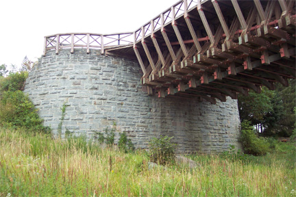
Abutment – A structure supporting the shore end of a bridge or pier.
Abutment

Batter Pile – A pile intentionally driven out of plumb to resist lateral movement. Less commonly known as a brace pile
Batter Pile

Beam – Any structural member carrying weight from one support to another.

Bearing Pile – Plumb piles bearing the weight of a structure.

Bent – A row of piles fastened together.

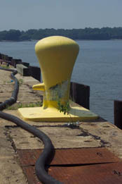
Bollard – A mooring device.
Bollard

Bracing – Horizontal or inclined structural members connecting piles in a bent used to increase lateral stability. Inclined members often form an “X” and are called X braces. Horizontal braces are commonly referred to as clamps as they are often paired one on each side of the pile bent thereby “clamping” the piles between them.

Bulkhead – A retaining wall or barrier.

Buttress – A brace on a retaining wall.

Caisson – Any large diameter shaft excavated inside of a protective casing to bearing strata.

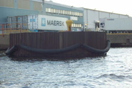
Camel – A floating log timber in front of a dock to keep ships away from the dock.

Cantilever – A projecting portion of a structure supported at one end only.

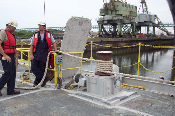
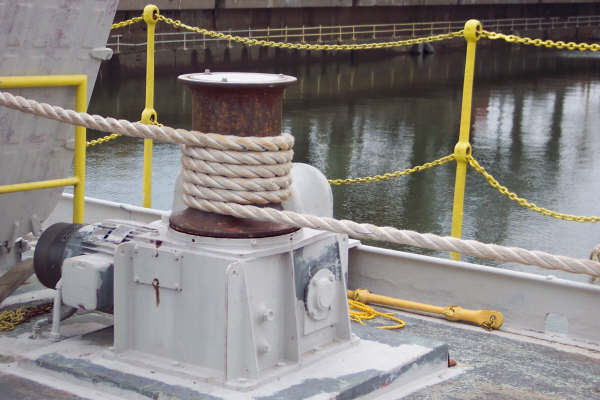
Capstan – Rotating spool used to pull heavy lines.

Capstan Capstan

Cat Walk – Walkway beneath a dock.

Cell – A round cofferdam constructed of sheet piles.
Cell

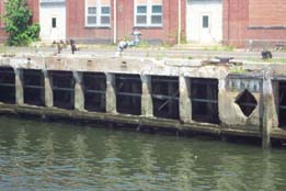
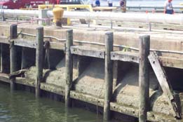
Chock – A piece of timber used as a separator between piles or timbers. Fender systems on piers were constructed of vertical members called fenders separated by horizontal chocks.

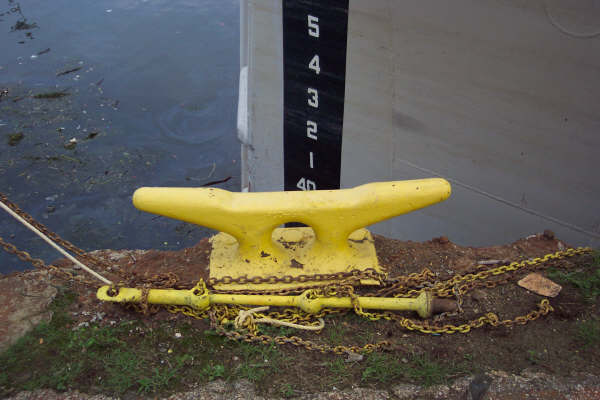
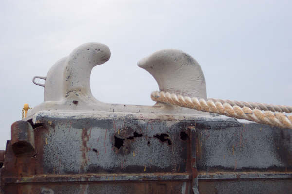
Cleat Mooring device – Line is placed in a figure eight around the horns to fasten lines from vessels.

Cleat

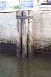
Cluster – A group of closely driven piles often used as a fender, mooring point or breasting surface.
Cluster

Cofferdam – Any dam used to exclude water from a construction site. Most commonly constructed of steel sheets today.

Column – A structural member carrying its load vertically.
Columns Columns

Creosote – Coal tar, heated and forced into timbers under pressure to act as a preservative.

Crib – A heavy timber box often filled with stones, sand or mud.

Cross Bracing – Inclined structural members connecting piles in a bent used to increase lateral stability. Also known as “X” bracing.

Cutoff Wall – Interlocked sheet pile wall designed to prevent the loss of fill at the interior side of a relieving platform.

Deadman – Any buried member serving as an anchor for the structure it is attached to.

Dead Load – The weight of the structure itself.

Deck – Structural member in a horizontal plane serving as a surface or floor of a pier, dock or wharf.

Diaphragm – A stiffening member between the flanges of a beam or girder also a connecting sheet pile wall between adjacent sheet pile cells.

Dolphin – A structurally independent section of a pier designed for mooring and or breasting of vessels. Similar in function to a cluster but structurally more complex.
Dolphin

Drift Pin – A metal rod driven into a tightly fitting hole bored through two pieces of timber.

Eccentric loading – Condition arising from piles driven out of plumb.

Embedment – Length of piling driven into the earth. Many older piers have slips dredged deeper to accommodate ships with a deeper draft than those they were designed to accommodate. The dredged slip may approach the embedded depth of the piles adversely affecting the stability of the pier.

Encasement – Any structure surrounding a section of piling intended to protect or repair that piling

End bearing pile – A pile transmitting its load axially to a firm bearing surface.

False work – Temporary piles and or structure designed to aid in the construction of a structure.

Fairlead – Device mounted on the side of a vessel meant to guide a line, prevent it from moving laterally and allow it to lead over the edge of the vessel without chaffing.

Fairlead

Fender Pile – Any non bearing pile driven to act as protection for a marine structure.
Fender Pile Chocks

Footing – A structural member designed to distribute the load to the bearing materials or bearing piles.

Friction pile – A pile depending upon friction between its surface and the surrounding material it is embedded in to support its load.

H-pile – Structural steel member with an H shaped section used as a pile.

King Pile – The center pile in a dolphin or cluster used to place mooring lines around.

Knee Brace – A short diagonal brace.

Lagging – Timbers placed between plumb piles to retain earth or fill.

Live Load – The moving or non permanent load a structure is designed to support in addition to the dead load.

Mooring Piles – Piles specifically installed to provide mooring for a vessel.

Mudsill – A timber structure placed in the mud as a support.

Pier – An intermediate  structural support between the abutments of a bridge. A Marine structure protruding out into the water in such a manner as to provide docking facilities perpendicular to the shore line.

Pier

Pile – A structural member placed in the ground to transmit a load to a firm bearing surface.

Pile Bent – Two or more piles driven in a row transverse to the long dimension of a structure and fastened together by means of bracing and capping.

Pile Cap – A structural member placed on the top of a line of piles to distribute the load of the structure above to the head of the piling.

Pile clamps – Horizontal braces installed so as to clamp the piling between them. They are often installed at the head and low water mark of piles on high deck piers.

Pipe pile – Pipe used as a pile.

Plumb Pile – Pile installed as close to vertically as possible.

Prestressed Pile – Pile constructed of concrete and steel reinforcement installed under tension.

Retaining Wall – A wall designed to hold back earth or fill.

Sheet Pile – Piles, often with a lock connecting them, driven next to each other to retain earth, fill or water.

Shim – Any small piece of wood or metal designed to fill a gap between structural members.

Shoring – Temporary braces.

Soldier Pile – One of a line of piling driven so as to allow the placement of lagging between them, often used to secure the banks of an excavation.

Spall – An irregular dish shaped depression left when a small area of concrete is broken off due to mechanical damage or rusting and expansion of the reinforcement rods.

Spliced Pile – Two or more pile sections joined to make one pile.

Stringer – Structural members connecting pile caps.

Tremie – A method of installing concrete under water, also the finished product.

Wakefield Piles – A sheet pile constructed of three planks so as to leave a groove on one side and a protrusion on the other. Often used to construct cut off walls.

Waler – A horizontal structural member designed to hold the heads of sheet piles in line and often connected to a dead man.
Waler Sheet Pile

Descriptive Terminology of Marine Structures Conditions

Good
Fairly new construction with no repairs or major maintenance required. Continued routine inspections are suggested.

Fair
Structures found to be in serviceable condition with no major wear or deterioration noted. Minor repairs and maintenance required. Continued routine inspections suggested.

Poor
Significant deterioration noted. The serviceability of the structure may be compromised. Inspection report should be reviewed by a qualified structural engineer and a repair program implemented. Annual inspections suggested.

Hazardous
Major deterioration noted. The serviceability of the structure is compromised. Inspection report should be reviewed by a qualified structural engineer and a repair program implemented immediately.

Imminent Danger of Collapse.

Extreme deterioration of structural integrity noted. Structure should not be utilized prior to review of inspection report by a qualified structural engineer. Major repairs or replacement required.

Method for determining distance across an area you cannot cross

It is sometimes necessary to estimate distance such as across a river. The following method was taught to me by John Malatich, a hard hat diver I tended when I was breaking into the business.

1. Pick out a fixed object on the bank on the other shore. A tree works well. (A)

2. Walk up river and pick out another tree on the bank on your side of the river. (B)

3. Keeping the two trees lined up go away from the river for about the distance you guess the river might be wide. This distance is not critical so don’t worry if you have a hard time judging distance.

4. Now make a pile of rocks. (C)

You should now have three points forming a diagonal line across the channel.

5. On your side of the river measure the down river distance between tree two (B) and tree one (A) to make point (D).

6. Starting back at tree two (B) walk up river that same distance.

7. After reaching this point if you measure away from the river to where a line
perpendicular to the river would intersect the line you created with the two trees and the rock pile you will have the distance across the river.

Measuring a River

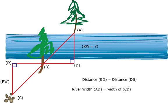
If your curious as to why this works – get your seventh grade geometry book out, like I did, and find out the minimum information you need to describe a right triangle. Obviously, if you know the lengths of all three sides you know what triangle you have. If you don’t have the length of all the legs, like in our case, you can also use the length of one leg and the angle two of the legs make when they intersect. Once you have a duplicate of the triangle on the river bank you just measure the distance across the river.

Tides

On the east coast of the United States, we experience semidiurnal tides.  These tides produce a cycle of one high and one low tide every 12.42 hours; that is, two tide cycles per day.  There are one-tide cycle areas (diurnal) in the Gulf of Mexico, the Philippines, and parts of Alaska.  There are also mixed tides.

Every 14.3 days, approximately twice a month, the earth, sun, and moon are aligned so as to form a straight line.  As you may readily imagine, the gravitational forces of each of these bodies reinforce each other to form higher than average tides.  These tides are called spring tides, and occur during the new and full moon.  Similarly, when the sun and moon are at right angles to the earth, every 14.3 days, the gravitational forces imposed on the earth are reduced, resulting in lower than normal tides called neap tides.

In general, at one of the two tidal cycles, there is a higher high tide.  This higher high tide is called the spring tide.  Therefore, the spring tide is not the result of snow or ice melt, or excess rain fall.  If we can imagine that the moon is closer to the earth during the first tidal cycle of the day, then during the second semidiurnal cycle, the moon will not be as close to the earth and, therefore, the gravitational influence will be reduced resulting in a lower high tide.

In our sun, moon, earth system, the sun is the largest body.  However, since the sun’s distance is so great from the earth, its gravitational influence on the earth’s tides is only forty six percent of that of the earth’s moon.  Consider the northwest winter winds blowing the ebb tide to the sea, our lowest low tides occur during the winter, and our highest high tides are spring tides that occur during the summer southeast wind influence.

The above information was excerpted from Michael Gabor’s 12/15/06 Tide Card letter.

Beaches and Waves

We are all waiting for the summer beach days and a few facts about beaches and waves may help us to endure the chill of winter.

  • “Berms” are flat, above water features that make up the beach
  • “Bars” are under water features; they are generally parallel to the beach, and are seldom seen except during unusually low water events.

On most beaches along our Atlantic Coastline, there is a constant exchange of sand between the berm and bar.  During storm conditions (winter months) when waves are high and follow close upon each other, the beach is eroded and the bar is built up.   During calm seas (summer months), the berm (beach) is built up at the expense of the bar.

  • Beaches extend about thirty feet (30’) outshore of low water
  • Although we are experiencing an increase in water elevation (we expect from global warming), our sea level has not significantly changed over the past 4,000 years.
  • Waves are moving forms but the water stays in the same place.  That is, if you were to place a floating object, as the waves gain height outshore of the beach, you would find that the float, and the water around it, move in a slow, circular oscillation, as each wave passes.  The wave breaks when the depth of water is reduced by the bar or beach.
  • While fishing or crabbing, you may find it useful to calm the waters around your boat.  This can be accomplished by placing fish oil, cod liver oil, or other viscous animal oil, in a canvas bag filled with rags, and then hanging the bag overboard.  Leaking two quarts an hour will calm the sea as much as one hundred feet (100’) around the boat.  Petroleum products do not work.


The above was excerpted from Michael Gabor’s tide card letter of 12/20/2005.

Phonetic Alphabet

A – ALPHA
B – BRAVO
C –
CHARLIE
D – DELTA
E – ECHO
F – FOXTROT
G –
GOLF
H –
HOTEL
I –
INDIA
J –
JULIET
K-
KILO
L –
LIMA
M –
MIKE
N –
NOVEMBER
O –
OSCAR
P-
PAPA
Q –
QUEBEC
R –
ROMEO
S –
SIERRA
T –
TANGO
U –
UNIFORM
V –
VICTOR
W-WHISKEY
X-RAY
Y-YANKEE
Z –
ZEBRA